So, wasn't the previous project interesting? I know it was! You might have noticed, that I am slowly, but steadily increasing the application of different sensors in real life. Also, I am making the code more complex. This is actually good because it will help you judge yourself.
Now, let's see what this project is all about.
What this project does?
Measure the ambient light level using an LDR and display it on the 16X2 LCD. Also show whether it's very dark, dark, bright and very bright according to some if else statements. Refer to the code to understand. We'll measure the light level in %. Out of a total of 1023 integers, 0 represents 0% and 1023 represents 100%.
Check this project out for the basic usage of 16X2 LCD.
Let's know the basics:
In the words of the great Wikipedia:
A photoresistor or light-dependent resistor (LDR) or photocell is a light-controlled variable resistor. The resistance of a photoresistor decreases with increasing incident light intensity; in other words, it exhibits photoconductivity.And it looks somewhat like this:

Don't mistake it for a photocell. A photocell develops a potential difference across it's terminals when the ends are connected to an external load, thus behaving like a battery.
Contrary to the photocell is the LDR, as the name suggests, it changes it's resistance according to the light falling on it. More is the light, lesser is the resistance.
Materials Required:
1. An LDR [Photoresistor]
2. Arduino
3. Jumpers
4. One 16X2 LCD
5. Four 1K and One 10K resistor.
6. Breadboard
7. and of course, a PC with Arduino IDE installed!
Procedure:
Hardware part:
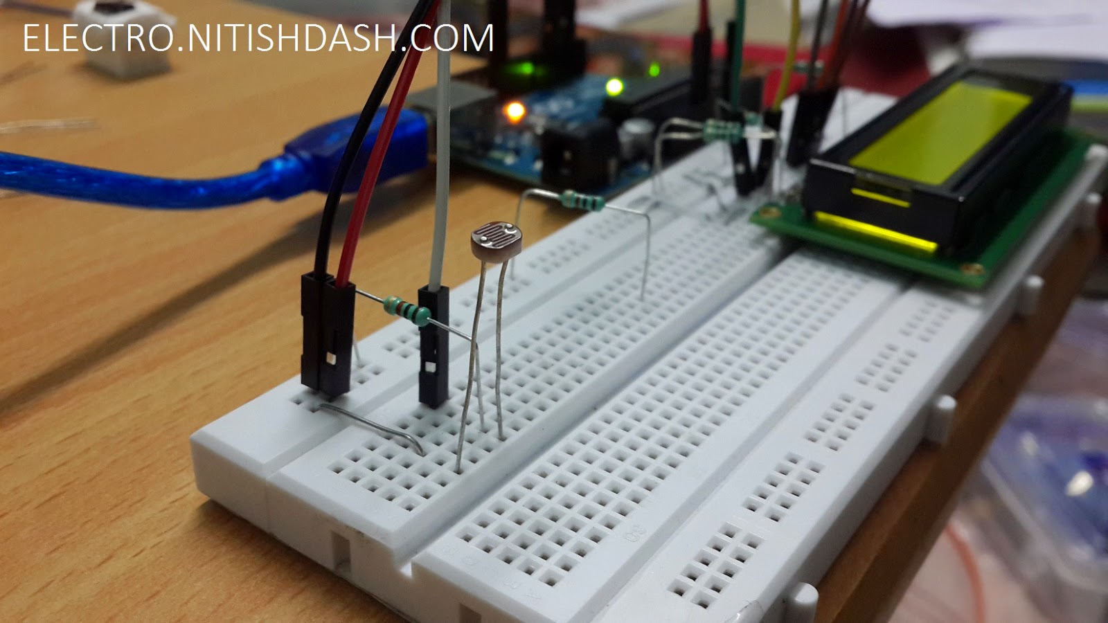
1. Make the connections as shown:


Software part:
1. Upload the sketch given below.
2. Power on the Arduino.
NOTE: ALWAYS UPLOAD THE SKETCH TO ARDUINO FIRST, THEN DISCONNECT THE ARDUINO AND THEN CONNECT ALL COMPONENTS!
Sketch:
/* * ON PUBLIC DOMAIN * Author : Nitish Dash * Name : LDR Light Level Display on 16X2 LCD * Created : 12/27/2014 * Webpage : http://goo.gl/Er9y4l * Author Email : nitishdash95@gmail.com * Author Website : http://www.nitishdash.com/ **** DONOT COPY AND PLAGIARATE WITHOUT THE AUTHOR'S PERMISSIONS **** */ #includeLiquidCrystal lcd(12, 11, 5, 4, 3, 2); void setup() { //initialise for at least 2s lcd.begin(16, 2); lcd.print("INITIALISING"); delay(500); lcd.print("."); delay(500); lcd.print("."); delay(500); lcd.print("."); delay(500); lcd.print("."); delay(500); } void loop() { int sensorValue = analogRead(A0); double dV = sensorValue; double le = (dV/1023)*100; int level = le; lcd.clear(); lcd.setCursor(0, 0); lcd.print("LIGHT LEVEL:"); lcd.print(level); lcd.print("%"); lcd.setCursor(0, 1); if ((level >= 0) && (level <= 5)) { lcd.print("VERY DARK"); } else if ((level > 5) && (level <= 10)) { lcd.print("DARK"); } else if ((level > 10) && (level <= 50)) { lcd.print("BRIGHT"); } else { lcd.print("VERY BRIGHT"); } delay(500); }
NOTE: PLEASE REMOVE LINE 60 BEFORE UPLOADING THE SKETCH.
How this works (Algorithm):
OK, let's start from ground zero. The analog input pins A0 to A5 on the Arduino UNO are capable of taking the signal and printing the voltage across it to the serial monitor. For example, if I connect the A0 pin to GND pin of the Arduino, by using a simple code, I can see in the Serial Monitor a value of 0. And when I connect the A0 to 5V pin, I can see a reading of 1023. So, simply put, when the A0 is given a voltage of 5V(HIGH SIGNAL) it corresponds to a value of 1023(MAX) and when it's given a voltage of 0V(LOW), it corresponds to 0. So, the analog pin can measure any voltage between 0-5V and it send a value between 0-1023 to the arduino for it to understand. So this means, by developing any voltage on this pin, you can measure a value between 0-1023.
This concept was used in the project. Since an LDR changes it's resistivity according to change in the amount of light it is being subjected to. So, it can increase or decrease the flow of electric current though the circuit. And as we know, potential drop across any component is V=IR (where I is the total current in the circuit, we can change the potential drop across the LDR. To limit the current, we've used a 1K resistor. To change the sensitivity, you may change the value of resistance.
This concept was used in the project. Since an LDR changes it's resistivity according to change in the amount of light it is being subjected to. So, it can increase or decrease the flow of electric current though the circuit. And as we know, potential drop across any component is V=IR (where I is the total current in the circuit, we can change the potential drop across the LDR. To limit the current, we've used a 1K resistor. To change the sensitivity, you may change the value of resistance.
Something for you!
Try these ideas to enhance your knowledge and test yourself:
1. Use both the DHT11 sensor and LDR to display Light Level and Temperature
2. Use the LDR to display direct values from 0-1023 on lcd.
2. Use the LDR to display direct values from 0-1023 on lcd.
This comment has been removed by the author.
ReplyDeleteLetters must be LiquidCrystal.h
ReplyDeleteThank you for sharing your idea mister :D
ReplyDeleteu just saved one of my experiments
I really like your blog and I also recommend you to check out Photocell Sensor Manufacturers in Odisha. Thank you
ReplyDeleteThanks for sharing very helpful information. I found another Photocell Sensor, site , they provide very helpful services.
ReplyDelete