Find fresh tutorials related to Arduino, Raspberry Pi, 555 Timer and many more microcontrollers. Learn something new everyday!


Showing posts with label 16X2 LCD. Show all posts

Tuesday, 30 December 2014

Interfacing a 16X2 LCD with Arduino - Displaying "Hello, World!" [ARDUINO]


You might have seen me using the 16X2 JHD16A LCD many times in my tutorials. Many of you might be new to this component. So what is the 16X2 LCD all about? Let's see.

What this tutorial does?
Teaches you the basics of an JCD16A 16X2 LCD, including the pin mapping, hardware and controlling it. and lets you display "Hello, World!" on the LCD with an Arduino. In the many upcoming articles and tutorials, we'll keep learning new ways of displaying messages and learn how to scroll the letters. We'll also create small animations too. But, in this one, we'll simply display "Hello, World!" in the first row and "Arduino is Fun." in the second.


Let's Learn The Basics! 
The JHD16A is a pretty popular module among the tinkerers mainly because it's cheap, and a perfect output device for many projects. It's also small. There might be many other alternatives and manufacturers. But the one I bought is made by JHD. When you buy the module, you might not get the headers soldered. There are 16 ports on it, which can be soldered to headers or directly to wires(if your project is permanent). But still I would suggest you to solder headers on it, because even if your project is permanent, you might occasionally need to check the health of your components in the project and that  in turn, would require maintenance. But again, that's entirely upto you.

If you are poor at soldering, I recommend you to read these articles:


The JHD16A is based on the Hitachi HD44780 . (Read more here: Hitachi HD44780 LCD controller) And the good thing is that, the Arduino 1.0.6 IDE, has inbuilt support for this controller. So, there's no need of downloading any library! We can get started easily.

Now, some geeky stats about the JHD16A module:

The pin config:

Copyrights: Instructables


 Pin No.
 Function of the pin
 Name
1
Ground (0V)
    VSS
2
Supply voltage; 5V (4.7V – 5.3V)
    VCC
3
Contrast adjustment; through a variable resistor
    VEE
4
Selects command register when low; and data register when high
    RS
5
Low to write to the register; High to read from the register
    R/W
6
Sends data to data pins when a high to low pulse is given
    E
7
8-bit data pins
    DB0
8
    DB1
9
    DB2
10
    DB3
11
    DB4
12
    DB5
13
    DB6
14
    DB7
15
Backlight VCC (5V)
    LED+
16
Backlight Ground (0V)
    LED-

PLEASE, NOTE THAT THE TOP LEFT PIN IS PIN NO.1. THIS IS BECAUSE, IN MY LCD, THE "JHD 16A" WAS PRINTED UPSIDE DOWN, WHICH MADE ME PRETTY CONFUSED! REFER THIS PICTURE:


Also, we shall never use the 4 pins DB0, DB1, DB2 AND DB3, because, we'll be using only the 4-bit mode everytime we print something on the LCD. So, it's completely safe to ignore it!


Materials Required:
1. PC with Arduino IDE installed!
2. Arduino UNO or NANO or PRO MINI
3. Jumpers
4. One 16X2 LCD
5. Three 1K and one 10K resistor.
6. Breadboard


Procedure:
Software part:
1. FIRST UPLOAD THE SKETCH WITHOUT CONNECTING ANY COMPONENTS ACROSS THE ARDUINO PINS

2. Don't power on the Arduino, yet.

Hardware part:
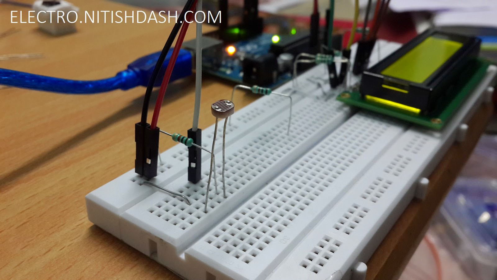
1. Make the connections as shown: Please remember this config because we'll never ever change this configuration in any of the tutorials.


THE SETUP


Now, power on the arduino.


Sketch:

/* 
 * ON PUBLIC DOMAIN
 * Author         : Nitish Dash
 * Name           : HELLO WORLD Display on 16X2 LCD
 * Created        : 12/30/2014
 * Webpage        : http://goo.gl/NjOEsH
 * Author Email   : nitishdash95@gmail.com
 * Author Website : http://www.nitishdash.com/
 **** DONOT COPY AND PLAGIARATE WITHOUT THE AUTHOR'S PERMISSIONS ****
 */
#include 

LiquidCrystal lcd(12, 11, 5, 4, 3, 2);

void setup() {
  lcd.begin(16, 2); //column and rows 
  lcd.print("Hello, World!");
  lcd.setCursor(0, 1);
  lcd.print("Arduino Is Fun.");
}

void loop() {
}

Please take care to remove the line 24 from the code before uploading
How this works (Algorithm):
It's simple. The command:
lcd.begin(16, 2);

initialises the LCD.

By using the command:
lcd.print("TEXT HERE");

we can easily print any text to the LCD (upto 16 characters).
To shift the cursor to 2nd row, use the command:
lcd.setCursor(0, 1);
and then again you can use:
lcd.print("TEXT HERE, AGAIN");

to print.

Video:
Coming soon.....


Downloads:
1. 16X2 LCD JHD16A DATASHEET
2. sketch.ino

Something for you!
Try these ideas to enhance your knowledge and test yourself:


Saturday, 27 December 2014

Using LDR to display light level on 16X2 LCD [ARDUINO]


So, wasn't the previous project interesting? I know it was! You might have noticed, that I am slowly, but steadily increasing the application of different sensors in real life. Also, I am making the code more complex. This is actually good because it will help you judge yourself.

Now, let's see what this project is all about.

What this project does?
Measure the ambient light level using an LDR and display it on the 16X2 LCD. Also show whether it's very dark, dark, bright and very bright according to some if else statements. Refer to the code to understand. We'll measure the light level in %. Out of a total of 1023 integers, 0 represents 0% and 1023 represents 100%.

Check this project out for the basic usage of 16X2 LCD.

Let's know the basics:
In the words of the great Wikipedia:
A photoresistor or light-dependent resistor (LDR) or photocell is a light-controlled variable resistor. The resistance of a photoresistor decreases with increasing incident light intensity; in other words, it exhibits photoconductivity.
And it looks somewhat like this:


Don't mistake it for a photocell. A photocell develops a potential difference across it's terminals when the ends are connected to an external load, thus behaving like a battery.
Contrary to the photocell is the LDR, as the name suggests, it changes it's resistance according to the light falling on it. More is the light, lesser is the resistance.


Materials Required:
1. An LDR [Photoresistor]
2. Arduino
3. Jumpers
4. One 16X2 LCD
5. Four 1K and One 10K resistor.
6. Breadboard
7. and of course, a PC with Arduino IDE installed!

Procedure:
Hardware part:
1. Make the connections as shown:


Software part:
1. Upload the sketch given below.
2. Power on the Arduino.

NOTE: ALWAYS UPLOAD THE SKETCH TO ARDUINO FIRST, THEN DISCONNECT THE ARDUINO AND THEN CONNECT ALL COMPONENTS!

Sketch:

/* 
 * ON PUBLIC DOMAIN
 * Author         : Nitish Dash
 * Name           : LDR Light Level Display on 16X2 LCD
 * Created        : 12/27/2014
 * Webpage        : http://goo.gl/Er9y4l
 * Author Email   : nitishdash95@gmail.com
 * Author Website : http://www.nitishdash.com/
 **** DONOT COPY AND PLAGIARATE WITHOUT THE AUTHOR'S PERMISSIONS ****
 */
 
#include 
LiquidCrystal lcd(12, 11, 5, 4, 3, 2);

void setup() { //initialise for at least 2s
  lcd.begin(16, 2);
  lcd.print("INITIALISING");
  delay(500);
  lcd.print(".");
  delay(500);
  lcd.print(".");  
  delay(500);
  lcd.print(".");
  delay(500);
  lcd.print(".");  
  delay(500);
}
void loop()
{
 int sensorValue = analogRead(A0);
 double dV = sensorValue;
 double le = (dV/1023)*100;
 int level = le;
 lcd.clear();
 lcd.setCursor(0, 0);
 lcd.print("LIGHT LEVEL:");
 lcd.print(level);
 lcd.print("%");
 lcd.setCursor(0, 1);
 
 if ((level >= 0) && (level <= 5))
 {
  lcd.print("VERY DARK"); 
 }
 else if ((level > 5) && (level <= 10))
 {
  lcd.print("DARK"); 
 }
 else if ((level > 10) && (level <= 50))
 {
  lcd.print("BRIGHT"); 
 }
 else 
 {
  lcd.print("VERY BRIGHT"); 
 }
 
 delay(500); 
}

NOTE: PLEASE REMOVE LINE 60 BEFORE UPLOADING THE SKETCH.

How this works (Algorithm):
OK, let's start from ground zero. The analog input pins A0 to A5 on the Arduino UNO are capable of taking the signal and printing the voltage across it to the serial monitor. For example, if I connect the A0 pin to GND pin of the Arduino, by using a simple code, I can see in the Serial Monitor a value of 0. And when I connect the A0 to 5V pin, I can see a reading of 1023. So, simply put, when the A0 is given a voltage of 5V(HIGH SIGNAL) it corresponds to a value of 1023(MAX) and when it's given a voltage of 0V(LOW), it corresponds to 0. So, the analog pin can measure any voltage between 0-5V and it send a value between 0-1023 to the arduino for it to understand. So this means, by developing any voltage on this pin, you can measure a value between 0-1023.

This concept was used in the project. Since an LDR changes it's resistivity according to change in the amount of light it is being subjected to. So, it can increase or decrease the flow of electric current though the circuit. And as we know, potential drop across any component is V=IR (where I is the total current in the circuit, we can change the potential drop across the LDR. To limit the current, we've used a 1K resistor. To change the sensitivity, you may change the value of resistance.


Something for you!
Try these ideas to enhance your knowledge and test yourself:
1. Use both the DHT11 sensor and LDR to display Light Level and Temperature
2. Use the LDR to display direct values from 0-1023 on lcd.


Measuring Distance with HC-SR04 Ultrasonic Module on 16X2 LCD PART-2 [ARDUINO]


So, I hope you might have got the idea of the working of the HC-SR04 Ultrasonic Distance Module. If not, read the part - 1 of the tutorial here: Measuring Distance with HC-SR04 Ultrasonic Ping Sensor and Arduino PART-1 [ARDUINO]

Also, I would recommend you to check out the previous article which used an LCD to display the temperature and humidity. Because I haven't changed the LCD connection. I only changed the HC-SR04 connection scheme.

Well, this is a simple continuation of the the tutorial. In the previous part we used a serial monitor to see the distance. This is quite inconvenient if you want to make the project more portable and small. Also, at many times, you'll need to show data on the 16X2 LCD. This project will be quite helpful to you t see how the data is displayed on the 16X2 LCD.

What this project does?
Calculate the distance of the object from the sensor and print the distance in centimeters on an 16X2 LCD.

I'm skipping the "Let's Know The Basics" part, because in the beginning I've already mentioned the links to previous posts. I've mentioned everything in those 2 posts.

Materials Required:
1. An HC-SR04 Ultrasonic Ping Sensor
2. Arduino
3. Jumpers
4. One 16X2 LCD
5. Three 1K and one 10K resistor.
6. Breadboard
7. and of course, a PC with Arduino IDE installed!

Procedure:
Hardware part:
1. Make the connections as shown:


REFERENCE:


Software part:
1. Upload the sketch given below.
2. Power on the Arduino.


Sketch:

/* 
 * ON PUBLIC DOMAIN
 * Author         : Nitish Dash
 * Name           : Measuring Distance with HC-SR04 on 16X2 LCD 
 * Created        : 12/27/2014
 * Webpage        : http://goo.gl/qcpuCa
 * Author Email   : nitishdash95@gmail.com
 * Author Website : http://www.nitishdash.com/
 **** DONOT COPY AND PLAGIARATE WITHOUT THE AUTHOR'S PERMISSIONS ****
 */
 
#include 
#define trig 10
#define echo 9
LiquidCrystal lcd(12, 11, 5, 4, 3, 2);

void setup() { //initialise for at least 2s
  pinMode(trig, OUTPUT);
  pinMode(echo, INPUT);
  lcd.begin(16, 2);
  lcd.print("INITIALISING");
  delay(500);
  lcd.print(".");
  delay(500);
  lcd.print(".");  
  delay(500);
  lcd.print(".");
  delay(500);
  lcd.print(".");  
  delay(500);
}
void loop()
{
  long time, dist;
  digitalWrite(trig, LOW); 
  delayMicroseconds(2); 
  digitalWrite(trig, HIGH);
  delayMicroseconds(10); 
  digitalWrite(trig, LOW);
  time = pulseIn(echo, HIGH);
  dist = ((time/2) / 29.1); //measure in cms
 if (dist >= 200 || dist <= 0)
 {
   lcd.clear();
   lcd.setCursor(0, 0);
   lcd.print("Distance: ");
   lcd.setCursor(0, 1);
   lcd.print("Out of range!");
 }
 else 
 {
   lcd.clear();
   lcd.setCursor(0, 0);
   lcd.print("Distance: ");
   lcd.setCursor(0, 1);
   lcd.print((int)dist);
   lcd.print(" cms");
  }
 delay(700); //modify but don't go below 500 ms
}

NOTE:Please remove the line 61 before uploading.

How this works (Algorithm):
Refer to the previous two posts here to know more:
1. Measuring Distance with HC-SR04 Ultrasonic Ping Sensor and Arduino PART-1 [ARDUINO]
2. Temperature and Humidity display on 16X2 LCD with DHT11 Sensor [ARDUINO]

Video:
Coming soon.....

Downloads:

Something for you!

Try these ideas to enhance your knowledge and application:
1. Display the distance in feet and inches
2. Combine Part-1 with Part-2 and glow a red led when distance is less than 20cms.


Friday, 26 December 2014

Temperature and Humidity display on 16X2 LCD with DHT11 Sensor [ARDUINO]


Hello. Recently I purchased a couple of sensors to use with  my Arduino. One of them is the DHT11 Temperature and Humidity sensor. This sensor is a cheap one. I got it in India for around $1.5. I'll mention the links if you want.

What this project does?
Displays the temperature (in Centigrade) and relative humidity (in %) received from the DHT11 sensor on the 16X2 LCD.

Let's know the basics!
"DHT11 Temperature & Humidity Sensor features a temperature & humidity sensor complex with a calibrated digital  signal output. By using  the exclusive digital-signal-acquisition technique  and  temperature  &  humidity  sensing  technology,  it  ensures  high  reliability and excellent  long-term  stability.  This  sensor  includes  a  resistive-type  humidity  measurement component  and  an  NTC  temperature  measurement  component,  and  connects  to  a  high-performance  8-bit microcontroller,  offering  excellent  quality,  fast  response,  anti-interference ability and cost-effectiveness."

Source: http://www.exp-tech.de/

SPECS:
Relative humidity
Resolution: 16Bit
Repeatability: ±1% RH
Accuracy: At 25℃ ±5% RH
Interchangeability: fully interchangeable
Response time: 1 / e (63%) of 25℃ 6s
1m / s air 6s
Hysteresis: <± 0.3% RH
Long-term stability: <± 0.5% RH / yr in
Temperature
Resolution: 16Bit
Repeatability: ±0.2℃
Range: At 25℃ ±2℃
Response time: 1 / e (63%) 10S
Electrical Characteristics
Power supply: DC 3.5~5.5V
Supply Current: measurement 0.3mA standby 60μ A
Sampling period: more than 2 seconds

Pin Description:
1. VCC power supply 3.5~5.5V DC
2. DATA serial data, a single bus
3. NC, empty pin
4. GND ground, the negative power


From now on, forget about the pin 3.

Materials Required:
1. A DHT11 Sensor
2. Arduino
3. Jumpers
4. One 16X2 LCD
5. Three 1K and one 10K resistor.
6. Breadboard
7. and ofcourse, a PC with Arduino IDE installed!


Procedure:
Hardware part:
1. Connect the components as shown.


REFERENCE:
[Click to enlarge]


Software part:
1. Download this library: DHT
2. Extract the zip and you'll get a folder named: "DHT"
3. Copy this folder to [My Documents/Arduino/libraries]
4. Upload the sketch given below.
5. Power on the Arduino.

Sketch:

/* 
 * ON PUBLIC DOMAIN
 * Author         : Nitish Dash
 * Name           : Temperature and Humidity on 16X2 LCD with DHT11 Sensor
 * Created        : 12/26/2014
 * Webpage        : http://goo.gl/W5iB30
 * Author Email   : nitishdash95@gmail.com
 * Author Website : http://www.nitishdash.com/
 **** DONOT COPY AND PLAGIARATE WITHOUT THE AUTHOR'S PERMISSIONS ****
 */
 
#include 
#include 
#define dht_dpin A0
dht DHT;
LiquidCrystal lcd(12, 11, 5, 4, 3, 2);
//this section is for the symbol of degree
byte deg[8] = {
 0b01110,
 0b01010,
 0b01110,
 0b00000,
 0b00000,
 0b00000,
 0b00000,
 0b00000
};

void setup() { //initialise for at least 2s
  lcd.begin(16, 2);
  lcd.print("INITIALISING");
  delay(500);
  lcd.print(".");
  delay(500);
  lcd.print(".");  
  delay(500);
  lcd.print(".");
  delay(500);
  lcd.print(".");  
  delay(500);
  lcd.createChar(0, deg);
}
void loop()
{
 DHT.read11(dht_dpin); 
 lcd.clear();
 lcd.setCursor(0, 0);
 lcd.print(" TEMP    : ");
 lcd.print((int)DHT.temperature);
 lcd.write((uint8_t)0);
 lcd.print("C");
 lcd.setCursor(0, 1);
 lcd.print(" HUMIDITY: ");
 lcd.print((int)DHT.humidity);
 lcd.print(" %");
 delay(1000); //modify but don't delay for less than 1s
}

NOTE: Please remove the line 58 from the code while uploading.
How this works (Algorithm):
The arduino receives the analog signal from the DHT11 sensor via A0 pin. The received signal is interpreted and processed by the library. The arduino then prints the message and measurement of temperature and relative humidity every 1s.

To test the sensor, try touching the sensor.
NOTE: Keep the sensor in normal conditions. Don't use it in excessively humid atmosphere or subject it to direct sunlight.

Video:
Coming soon.....

Downloads:
1. sketch.ino
2. Breadboard schematics
5. DHT11 Library

Any doubts? Feel free to leave a comment.

Upcoming projects!

1. Programming ESP8266 using NodeMCU and LUA Scripts

2. IoT Applications

3. NRF42L01 2.4 GhZ module interfacing with arduino

4. ESP8266 - Everything cool about it!

Language ain't any barrier!

Get Updates!

Enter your email address:


Get the latest projects delivered into your inbox, hot!